
Vehicle Setup Adjustments and Build Tips
Use Threadlock! Tekno Vehicles have many metal-to-metal contacts throughout, prevent screws from backing out with a light dab of thread lock on each screw that threads into metal (do not use thread lock on screws that thread into plastic)
When building you diffs, take your time to make sure they go together correctly for a smooth and long lasting diff. Check out Ryan’s videos below for tips on building and making them smoother
Be careful when using a power screwdriver on screws that thread into plastic. Use a low clutch setting, and if necessary use a normal hex tool to check tightness
Use a dab of grease when building each of the CVDs, and make sure a film covers the entire ‘ball’ of each CVD before installing into the axle. Will drastically increase CVD life as well as improve handling.
Use a product such as Shock Snot on shock and diff O-rings to prevent swelling and oil seepage.
Our vehicles have adjustable hinge pin holders that allow users to fine-tune suspension geometry for different tracks, conditions or driving styles.
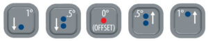
Using the hinge pin inserts , fine adjustments can be made to the location of each hinge pin. All 25 positions can be obtained by rotating the included seven inserts (indicated by color).
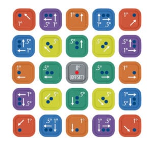
First, we start by understanding the “Base Angle” for each brace. Base Angle is obtained by using center-dot inserts ![]() in each brace and the degrees.
in each brace and the degrees.
Base Angles
- Sweep = 0°
- Kick-Up = 10°
- Toe = 3°
- Anti-Squat
- Composite “C” Block = 3°
- Aluminum “C” Block = 2°
Next, we take the difference of both insert from center-dot and add it to the Base Angle. For instance, when calculating the Kick-Up and you have double-dot up ![]() on “A” and double-dot down
on “A” and double-dot down ![]() on “B” the final angle would be 10° + 0.5° + 0.5° = 11°.
on “B” the final angle would be 10° + 0.5° + 0.5° = 11°.
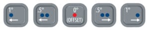
Note: From the center-dot position, only a maximum of 2° difference can be obtained by using single-dot offset inserts in opposing braces. For example ![]() in A and
in A and ![]() in B is 2°.
in B is 2°.
The attitude of the front hinge pins can be angled in or out to adjust Sweep or up and down to adjust Kick-Up. To find the proper insert combine the horizontal setting (Sweep) and the vertical setting (Kick-Up) using the colored insert chart above.
Sweep (Horizontal Adjustment)
This chart shows the amount of “sweep” in degrees. Inserts in the center horizontal position on both “A” and “B” would be 0°. Maximum of 2° can be obtained by using single dot out on A and single dot in on B.
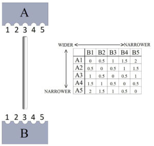
The picture (above) is top down, looking at the left side of the “A” and “B” hinge pin blocks. Positions 1 through 5 indicates moving the hinge pin left to right.
Kick-Up (Vertical Adjustment)
The chart right shows the amount “Kick-Up” in degrees. Inserts in the center vertical position on both “A” and “B” would be 10°. Maximum of 12° can be obtained by using single dot up on A and single dot down on B.
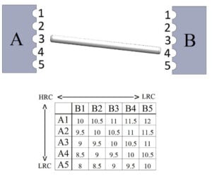
This picture is a side profile, looking at the left side of the “A” and “B” hinge pin blocks. Positions 1 through 5 indicates moving the hinge pin up and down.
The attitude of the rear hinge pins can be angled in or out to adjust Toe or up and down to adjust Anti-Squat. To find the proper insert combine the horizontal setting (Toe) and the vertical setting (Anti-Squat) using the colored insert chart at the top of this article.
Toe (Horizontal Adjustment)
The chart (shows the amount “Toe” in degrees. Inserts in the center horizontal position on both “C” and “D” would be 3°. Maximum of 5° can be obtained by using single dot in on C and single dot out on D.
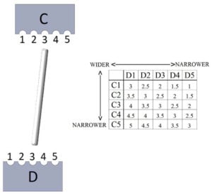
This picture is top down, looking at the left side of the hinge pin blocks. Positions 1 through 5 indicates moving the hinge pin left to right.
Anti-Squat (Vertical Adjustment)
The charts below show the amount “Anti-Squat” in degrees. Inserts in the center vertical position on both “C” and “D” would be 3° with the composite C brace and 2° with the aluminum brace. Maximum of 5° can be obtained by using single dot up on C and single dot down on D with the composite brace and 4° with the aluminum brace.
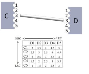
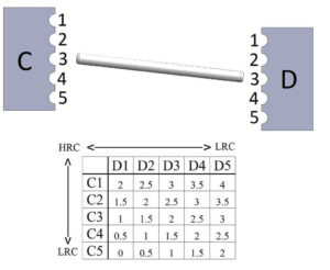
The pictures are a side profile, looking at the left side of the “C” and “D” hinge pin blocks. Positions 1 through 5 indicates moving the hinge pin up and down.
Some of our setups use pistons with custom hole configurations. For instance 4×1.9 (Four 1.9 mm holes).
To make these pistons use our TKR6160 – Shock Piston Blanks (CNC, flat/tapered, 16 dimples, 4pcs) and drill 4ea 1.9 mm holes evenly throughout the piston.
We recommend using this piston drill set for all sizes 1.05 to 2.0 mm or this drill set for 2.0 to 3.0 mm.
It’s important that your suspension is as free as possible and able absorb bumps and jumps instead transferring energy to the chassis and making your vehicle difficult to drive.
The best way to verify that your suspension is free and operating properly is to remove the shocks and tires and make sure the arm falls under their own weight. There should be no resistance when the arm falls and it should bounce a little when it hits the droop tabs.
Also, your hinge pins should be able to be inserted into the arm easily and turn easily. Tip: We do not recommend putting any lubricant on the hinge pins as it quickly attracts dirt.
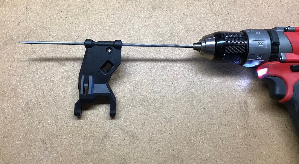
If you notice that your suspension appears to be binding, our first recommendation is to ream the arms. Our SCT410,
EB48, NB48, ET48, NT48 and EB48SL vehicles use an inner hinge pin diameter of 4.0 mm. 4 mm hinge pin reamers can be found online or a good option is to use a 5/32 round chain saw file. Using an electric drill, tighten the file in the chuck and run the file through the hinge pin hole at full speed a couple times. Periodically, insert the hinge pin in the arm and see if it rotates freely. If not repeat the process
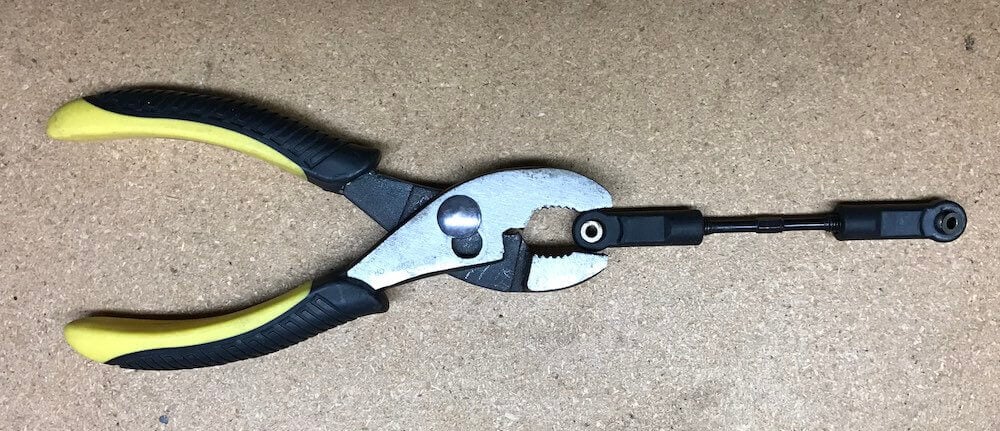
Check your camber links to verify they pivot freely. From time to time, they will need to be cleaned by removing the pivot ball and wiping the inside of the rod end with a microfiber cloth. If the pivot ball does not move freely in the rod end, one trick is to pinch the rod end with plyers when the ball is inserted. Pinching the rod end directly where it holds the pivot ball enlarges the opening slightly and provides more room for the pivot ball to move.